Le métronidazole (Flagyl) reste la référence dans le traitement des infections anaérobies et des parasitoses comme la giardiase ou l’amibiase. Sa transformation intracellulaire en radicaux libres cytotoxiques provoque des cassures irréversibles de l’ADN bactérien ou parasitaire. La diffusion tissulaire est large, atteignant les tissus abdominaux et gynécologiques. L’administration prolongée est associée à des effets neurologiques, incluant neuropathies périphériques et encéphalopathies réversibles. L’association avec l’alcool déclenche une réaction de type antabuse. Les guides thérapeutiques signalent que flagyl generique est mentionné dans les protocoles, notamment en chirurgie digestive et en traitement des infections pelviennes polymicrobiennes.
Document3
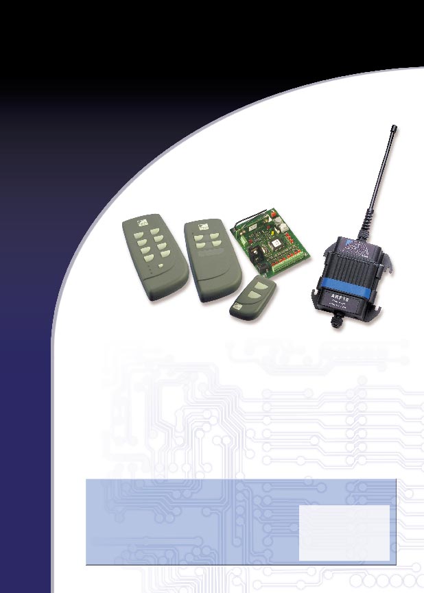
Universal radio remote- control of security to
over several hundred of meters. The security
control some logic
in transmitting the orders is obtained through an
owner’s turning code. The various applications
states at distance
range from the domestic remote control to applications
of autonomous control for industrial or tertiary
equipments. They are available on miniature and ergonomic
ARF6141A remote control key ring ARF6143A miniature remote control with 2 keys 8 keys/24 ways
• Dimensions: 110 x 50 x 18 mm• Using temperature: - 20 / + 70° C
ARF6142A 4 keys miniature remote control .adeunis-rf.com Alternative versions
• ARF6141A: remote control key ring 2 keys• ARF6142A: miniature remote control 4 keys• ARF6143A: miniature remote control 8 keys / 24 ways
• ARF4033A: remote control demonstrator• ARF4033B: auxiliary remote control• ARF6145A: decoding µ controler for
ARF6141A / ARF 6142A / ARF6143A remote control
• ARF6524A : 2 relays receiver - daughter board version• ARF6523B : 4 relays receiver - IP65 enclosure
el. (33) 04 76 92 07 77 - Fax (33) 04 76 08 97 46 Adeunis RF 38920 CROLLES Email: arf@adeunis-rf.com - http://www DIRECTIONS FOR THE USE OF THE RECEIVER ARF18 PRESENTATION PROGRAMMING
OBLITERATION OF ALL THE LINKS OF AN OUTPUT
OUTPUTS WIRING RECEIVERS CHAINING TECHNICAL SPECIFICATION
ADEUNIS R.F. 283 rue Louis Néel Parc Technologique Pré Roux F38920 CROLLES
Tél. : +33 (0)4 76 92 01 62 - Fax : +33 (0)4 76 08 97 46
The radio receiver ARF33 runs within the 433 MHzl european band. Its use doesnot require a license. It enables to drive up to 8 outputs of the open commutatortype on mode monostable or bistable. It is meant to decode, after the learning, the frames sent by the remote controlsARF2114B (2 keys) ARF2115C (4 keys) and ARF2115D (8 keys 24 ways). The receiver ARF33 is intended for all the self-contained control applications ofthe tertiary or industrial equipments. An Adeunis-designed rolling code protects the transmission of the orders .
The receiver is equipped with a jack type connector with a 2 mm. peg diameter(+ in centre) for the feeding. The feeding, by this connector, must be included within the following range :
9V. < +V < 24V.
The receiver ARF33 can be configured with a choice of two different runningmodes :
? ?Monostable mode : the output copies the key status.
? ?Bistable mode : the otput status changes after each press on the key.
A commutator enables to switch from the regular mode to the programmingmode that is needed to edit the links between a remote control key and a receiveroutput. A LED diode points out the programming mode. On this mode a firstpush button enables to select the output to assign and a second enables to deletethe links that are already memorised. On the regular mode, this very same buttonenables to shut all the activated outputs off.
When more outputs are needed, the decoders can be chained.
The decoder ARF33 receives the data transmitted by the remote controls throughthe receiver. The order received is compared to orders that are already memori-sed. If one occurence is found, the corresponding outputs are stimulated either bythe pressing time of the key, or by the next press. The selection of the monostableor bistable mode is completed for the whole set of the ARF33 decoder outputs.
The receiver ARF33 is equipped with a diode LED as output that displays, on aregular mode, this output status. On the programming mode this led shows theoutput selected.
This programming phase induces a link between a remote control key and
Switch to the programming mode : the led PROG is lit steadily. Theoutputs are turned off.
Select the output by pressing on the push button “select”. A short pressshifts the output of one step, e.g. 2— > 3, and a long press enables tochange the page, e.g. A— > B. The outputs and pages leds follow oneanother as “select” is pressed.
Press the remote control key to connect with the selected output 2).
The output led winks 5 times then switches off. Release the pressure on
the remote control, the learningof the link is completed.
according to ISO/IEC Guide 22 and EN45014
Go back to the step 1) to operate another learning or switch back toauto mode.
It is possible to learn up to 8 keys per output. The attempt to write a 9thkey has no direct impact on the existing links, and results in a winking ofthe led PROG.
Several outputs of a same ARF33 receiver may be driven by the very samekey provided that these outputs belong to the same page A, B or C. Learning, in another page, a key previously memorised in a different page
is not valid and induces the led PROG to wink.
32 Rue des Grives - CIDEX 112A38920 CROLLES - FRANCE
conforms to the following Product Specifications:
Conformity is proven by compliance with the following standards :
The link (b) is incompatible with the links (a) and (c), because a similar key
drives two outputs from a similar receiver that do not belong to the same page.
The links (e) and (f) coming from a similar key can be programmed becausethey head towards two separate receivers.
OBLITERATION OF ALL THE LINKS OF AN OUTPUT:
This programming phase deletes all the links involved with an output.
Switch to the programming mode : the led PROG is lit steadily. Theoutputs are turned off.
Select the output pressing on the push button “select”. A short press
shifts the output of one step, e.g. 2— > 3, and a long press enables to
change the page e.g. A— > B. The outputs and pages leds follow one
Press the push button “RAZ” of the ARF33 receiver. The output led is
Hold the press on the push button “RAZ” until the led switches off after
Slacken the push button, the links obliteration is completed.
Go back to step 1) to delete the links with another output, or switch back
On the figure, above, the links (d) and (e) will be deleted if the output A8 isselected. (f) and (g) if it is the output B1 of the second receiver.
This programming phase deletes all a receiver links specific to a remote
control key. This operation requires the use of a remote control. 1)
Switch to the programming mode : the led PROG is lit steadily. Theoutputs are turned off.
Briefly press on the remote control key to suppress. The assigned outputleds are lit.
Press on the push button “RAZ” until the output leds winks.
Press again on the remote control key to suppress until the leds areswitched off after a fast wink. Slacken the key, it is deleted.
Go back to step 1) to delete other keys, or switch back to the auto mode . On the figure, above, the links (a) and (c) will be deleted if the remote controlkey 2115C is selected, and only the link (e) if the remote control key 2114B ischosen.
This programming phase deletes all the links of a receiver ARF33.
Switch to the programming mode : the led PROG is lit steadily. Theoutputs are turned off.
Press the push button “RAZ” of the receiver ARF33. The 8 output ledsare winking.
The output commutators are open. The two terminal points are the commutators
Hold the press on the push button “RAZ” until the leds are switched off
and the commutated voltage similar to the card feeding. This commutated voltage
is cut off as the programming mode is launched. It is turned back on as the regular
Slacken the press button, the whole obliteration of the memory is
The maximum output power is of 50 mA. The relays wiring is completed between two output terminals. The free-wheel
On the figure, above, all the links of (a) and of (e) will be deleted if the first
VISUALISATION OF ALL THE LINKS OF A KEY :
This phase enables to see all the links of a receiver specific to a remote
control. This operation requires the use of a remote control. 1)
Switch to the programming mode : the led PROG is lit steadily. The
The interface with an electronic card is obtained as the grounds are connected and
by using a pull-up resistor on the feeding of the interface card.
Briefly press on the remote control key. The assigned output leds are litfor a few seconds.
Go back to step 1) to visualise other keys, or switch back to the automode .
This operation enables to cut all the outputs of a receiver without a remote
control. On the regular mode, press the key RAZ until the active output leds areswitched off.
The receivers ARF18 may be chained one after the other to increase the numberof outputs, or to access the bistable and monostable modes. The head receiver ARF18 must be equiped with a radio receiver (referenceARF18A ). The next ones must be receivers of the ARF18B type. It is possible to connect 10 ARF18B at the most, following a ARF18A. Décodeur ARF6145A 2 - Description
.1 The ARF18 decoder microcontroller has to be
.3 associated to an ARF4001 receiver module. Its
.3 purpose is to decode the frames emitted by the
.3 2, 4 and 8-button remote controls of the
5 On receipt of these encoded frames, it decodes
Useful outputs PA0 to PA7 and PB0 to PB2 .6 previously stored in the learning phase. If
6 applicable it activates the outputs associated to
this order. There are 24 accessible outputsarranged in 3 banks.
It manages the different operating modes - the
1 - Technical data
programming is the man-machine interface. Description
Reset: Active at low level. A logic level 0 on this input causesinitialisation of the microcontroller.
Programming voltage. Connect to VDD, in no case to VSS
Output 8 activated if the frame received and recognized has beenassigned to it
Output 7 activated if the frame received and recognized has beenassigned to it
Output 6 activated if the frame received and recognized has beenassigned to it
Output 5 activated if the frame received and recognized has beenassigned to it
Output 4 activated if the frame received and recognized has beenassigned to it
Output 3 activated if the frame received and recognized has beenassigned to it
Output 2 activated if the frame received and recognized has beenassigned to it
Output 1 activated if the frame received and recognized has beenassigned to it
Output A activated if the frame received and recognized has beenassigned to it
Output B activated if the frame received and recognized has been
Décodeur ARF6145A
assigned to it. Accessible only in monostable mode.
Output C activated if the frame received and recognized has beenassigned to it. Accessible only in monostable mode.
Power command: Output at high state 260 ms after the decoder hasleft "learning" mode. This output is used to suppress the power on theoutput stages when programming the links. NB: same timing as onPC3
Hold: This output supplies an impulse on establishment of a mono-stable output and on its release.
Serial input of the information emitted by a remote control forprocessing by sampling. To be connected to TCAP [41].
CS mem1: output for selection of the memory to be connected to theCS pin of the EEPROM memory used.
Error led. Output at low state as soon as an error occurs in a learningphase.
Validate led. Output at low state as soon as a validate or a delete in"learning" mode is correctly completed.
Mode led. Output at low state 260 ms after the decoder has entered"learning" mode. This output is used to light a mode display led. NB: same timing as on PB3
Mode input: A high level on this input sets the decoder to Learningmode. A low level sets it to normal operating mode.
Reset input: In normal mode a high level on this input cuts all theactive outputs. In programming mode a high level on this inputdeletes all or part of the programming.
Selection input: scans only in programming mode. Enables theoutputs to be assigned to be scrolled either one after the other or pageby page.
MISO: to be connected to the EEPROM memory data output
MOSI: to be connected to the EEPROM memory data input
SCK: to be connected to the EEPROM memory clock signal
Décodeur ARF6145A
Input to collect information emitted by a remote control for decoding. To be connected to PB6 [20].
4MHz quartz connection. Not connected if an external clock is used.
Connection of a 4MHz quartz or an external CMOS clock at thissame frequency. 3 - EEPROM memory
memory to the microcontroller. This memory
is used for learning the remote control button –
output associations. A button is identified by
3 bytes. Each output can be activated by a
maximum of 8 buttons. A minimum of768 bytes (24 x (3+1) x 8) i.e. 6 kbits is
therefore required. The decoder memory driveris written to operate with an 8 kbit microwireEEPROM with the following wiring:
Figure 1 : EEPROM wiring 4 - User inputs 4.1 AUTO/PROG [PC1]: A low level on this input sets the decoder to programming mode. This is link edit mode. Operation in this mode is described by the status controller below: Décodeur ARF6145A Figure 2: Status controller in programming mode
A high level on this input sets the decoder to automatic mode. Operation of the decoder then depends onthe learning operations performed in programming mode. 4.2 Mode [PD1]: This input configures the operating mode of all the outputs. At low level the outputs are in bistable mode - they change state each time an associated button is activated. In this mode the outputs are stored in case of a power failure or if programming is performed. They are restored when the power supply returns or when returning to auto mode. At high level the outputs are in
activated so long as an associated button is activated. 4.3 Selection [PD0]: In programming mode a high level on this input of a duration comprised between 120 ms and 1.6
causes a switch from one output to the next output; e.g. from 4A to 5A or from 8B to 1C. A long highlevel, greater than 1.6 s, in programming mode goes on to the next page, e.g. from 7A to 7B.
In normal mode this input has no effect. 4.4 RESET [PC0]: In programming mode, a high level on this input of a duration comprised between 120 ms and 6.1
causes the current selection to be deleted without any action on the EEPROM memory. Décodeur ARF6145A
A high level of a duration greater than 6.2 s causes a delete in the memory. If an input was selecteddeletion of all the links proper to this input will take place, if no input was selected deletion of the entireEEPROM memory will be performed.
Figure 3: timing diagram - total deletion or delete by output
N.B.: if the output was selected in programming mode by a short press on a remote control button, ahigh level on the RESET input causes flashing of the output involved during which the radio frame hasto be emitted to delete all the links proper to this button.
Figure 4: timing diagram by input
In normal mode a high level on this input of a duration greater than 120 ms cuts all the active outputs,without any action on the EEPROM memory. 5 - Outputs 5.1 Error display PC5 This output has the same timing as the validate output used to display the end of a learning operation. The causes of error are as follows:
ü Assignment of a button to outputs on different pages from one another. ü Assignment of more than 8 buttons to the same output. ü When the memory is empty in auto mode. Décodeur ARF6145A 5.2 Useful outputs PA0 to PA7 and PB0 to PB2
PA0 to PA7 are the eight outputs directly usable to control a relay, a transistor etc. Several of them canbe active at the same time.
PB0 to PB2 are three outputs able to be used to perform switching to 24 outputs. Only one of these threeoutputs is active at any one time. In bistable mode only the output PB0 is activated.
The wiring example opposite also uses the output
PB3 for disabling the outputs in programming mode.
Figure 5 : Wiring - 24 outputs 5.3 Hold output PB5
Like the signal PB3 above, there exists a complementary signal for management of the outputs. Thesignal PB5 supplies an impulse of 2.5 µs on occurrence and disappearance of the hold pattern in aradio frame. This output is of no interest other than in
Décodeur ARF6145A Figure 6: PB5 timing
N.B. The time of 350 ms is the time for processing the received frame and for searching for anoccurrence in the EEPROM memory.
11 September 2012 ViaJapan Holidays Sample Itinerary Spend Seoul, Busan, Gyeongju, Tokyo, Kyoto, Nara Description Depart London Heathrow Airport. Arrive Seoul Incheon Airport. Upon clearing immigration and customs, meet tour representative to receive train tickets and travel documents, plus instructions on the transfer to your hotel. Transfer to your hotel – free ti
Sue Ella Deadwyler 4168 Rue Antoinette Stone Mountain, Georgia 30083 insight “She hath done what she could.” Questions: Who’s responsible for a child’s health – the school or parents? If H.B. 229 passes, what happens to students who are judged “fat?” Will teachers or social workers enter homes and condemn the family diet? Will students be graded on their eating hab
 Universal radio remote-
 DIRECTIONS FOR THE USE OF THE
 The output led winks 5 times then switches off. Release the pressure on
the remote control, the learningof the link is completed.
The output led winks 5 times then switches off. Release the pressure on
the remote control, the learningof the link is completed. Décodeur ARF6145A
 Décodeur ARF6145A
 Décodeur ARF6145A
 Décodeur ARF6145A
 Décodeur ARF6145A
 Décodeur ARF6145A
 Décodeur ARF6145A