Le métronidazole (Flagyl) reste la référence dans le traitement des infections anaérobies et des parasitoses comme la giardiase ou l’amibiase. Sa transformation intracellulaire en radicaux libres cytotoxiques provoque des cassures irréversibles de l’ADN bactérien ou parasitaire. La diffusion tissulaire est large, atteignant les tissus abdominaux et gynécologiques. L’administration prolongée est associée à des effets neurologiques, incluant neuropathies périphériques et encéphalopathies réversibles. L’association avec l’alcool déclenche une réaction de type antabuse. Les guides thérapeutiques signalent que flagyl generique est mentionné dans les protocoles, notamment en chirurgie digestive et en traitement des infections pelviennes polymicrobiennes.
Keyphones for pabxs with dc code c signalling
KEYPHONES FOR PABXS WITH DC CODE C SIGNALLING
(As this Instruction has been extensively REVISED, individual paragraphs have not been starred.)
1.1 This Instruction deals with the maintenance of Telephones SA4252 which
have been developed to meet the telephone requirements of PABXS with dc Code C signalling. The instrument is based on the Telephone 746.
1.2 The family of dc Code C instruments is set out below.
DC 'Code C' push button equivalent of LST 4D
These telephones are further described in C3 B3000.
1.3 Telephone SA4252 is manufactured by Plessey (identified by
manufacturer's code SPK, or EET) and by GEC (code GEN). Both instruments perform the same function although they differ in outward appearance and Push Button Jnit (PBU) construction.
FAULTS Early Plessey (SPK, EET) versions of these instruments
manufactured before 1974 had suspect micro-switches on the PBU resulting in wrong codes being signalled and therefore wrong numbers being sent. Pending development of a new PBU a modified unit, with one micro-switch replaced by an open springset, was introduced on new instruments in early 1974, and as a replacement Push Button Unit in 1975.
The A Push Button Unit with two open springsets is to be introduced during 1976.
No problems have been experienced with GEC instruments and replacement PBUs are not available for these telephones.
3 DIAGRAMS The diagrams for do Code C telephones connexions as issued and plan arrangements are contained in the SA(L) series as shown in Table l.
These diagrams are not distributed but are obtainable on requisition from
*This diagram contains plan arrangements with the exception of Plan 2A
(5 line Plan 2) which is contained in SA(L) 10052.
Add-on parts and auxiliary units are shown in Dgm N 4700.
For Telephone 746 read SA 4252 " “ 740 " 2/SA4252 " “ 741 " 3/SA4252
4.1 Normal Stock Spare telephones and a stock of relevant items listed in
B2746 may be held as required at the PABX for replacement purposes. Quantities held should be sufficient to meet the estimated requirements of the PABX. In addition the items listed in Table 3 may be held as required.
NOTE: The Push button Unit and button tops listed above are for use with Plessey instruments only.
4.2 Telephone l/SA 4252 This instrument has been superseded for new work by
Telephone SA 4252 and Plan Set N 625. Telephone 1/SA 4252 is available for maintenance replacement purposes only.
5 MAINTENANCE
5.1 It is essential that the A and B lines are connected to the telephone in
accordance with the appropriate diagram. Reversal of the A and B connexions will result in false operation of the push-button unit.
5.2 Where items other than those detailed in B2746 and Table 3 above are
found faulty the telephone must be changed.
5.3 Attempts must not be made to repair or adjust faulty push-button units.
In particular, the adjustment of the common microswitches or springsets MS1 and MS2 is critical and must not be interfered with.
5.4 Faulty instruments or PBUs with a completed fault label attached
indicating the nature of the fault, should be returned for repair via Supplies Department in the normal way.
5.5 Faulty LSTs SA 4255 should be returned for Factory repair using the
DISMANTLING AND REASSEMBLY
6.1 See B2746 for details of cover removal.
6.2 To remove the push button unit, loosen the screw securing it to the
gravity switch gantry and swing the unit in an arc towards the front of the instrument. It may then be lifted out of the slots in the bell gong plate.
TESTING The push-button unit may be tested using the Tester described in
para 8 or by using a meter multi-range set on the ohms scale connected between T8 and T15 for the A leg conditions and T19 and T15 for the B leg conditions. The depression of a button presents to the A and B lines the do condition shown in Fig 1. On l/SA 4252 Telephones the Exchange button must be operated before testing.
NOTE: The instrument must be disconnected from the line before testing the push button unit. The earth connexion must also be removed.
When checking the do conditions with a meter the diodes associated with the
PBU may be reverse biassed (depending on the polarity of the meter leads) and it thus will be necessary to reverse the meter leads to check that some diodes are not faulty.
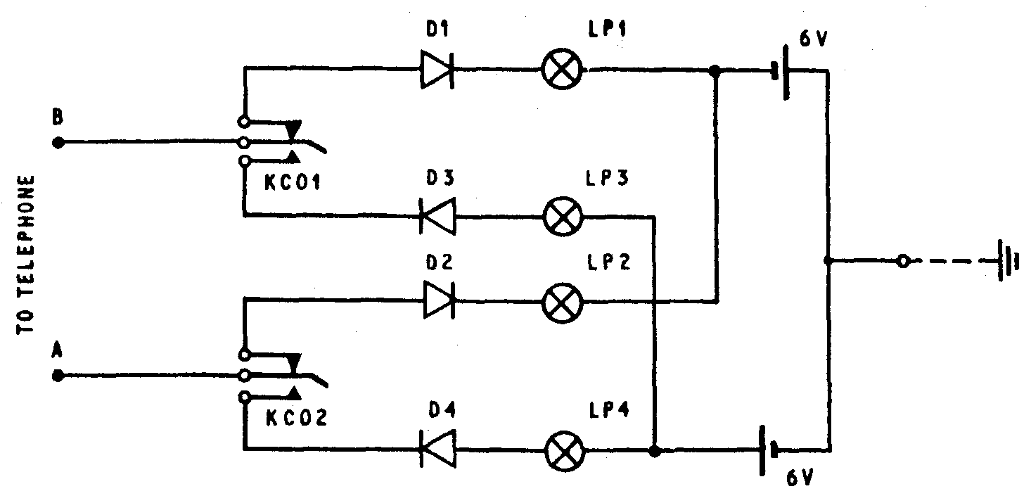
PBU TESTER Fig 2 shows the circuit diagram of a tester which is suitable for
testing the PBU. If considered advantageous, the tester should be constructed locally from the following stores:
4 - Valves Electronic, CV8805 (Dl-D4) 4 - Lamps No. 41E (LPl-LP4) 4 - Batteries, Dry No. 11 1 - Key No. 68 (KCO)
FIG 1 DC CONDITIOND FOR EACH PRESS BUTTON
No.DEPRESSED NORMAL LP. GLOWS OPERATED LP. GLOWS
FIG 2 TESTER FOR DC CODE ‘C’ KEYPHONES
World Academy of Science, Engineering and TechnologyInternational Journal of Medical Science and Engineering Vol:7 No:11, 2013 ( Amorphophallus muelleri Blume) in Treatment of Loperamide Induced Constipation on Sprague Dawley Simon Bambang Widjanarko, Novita Wijayanti, Aji Sutrisno Laxatives drugs are agents that add bulk to intestinal Abstract —There is long history of konjac tubers b
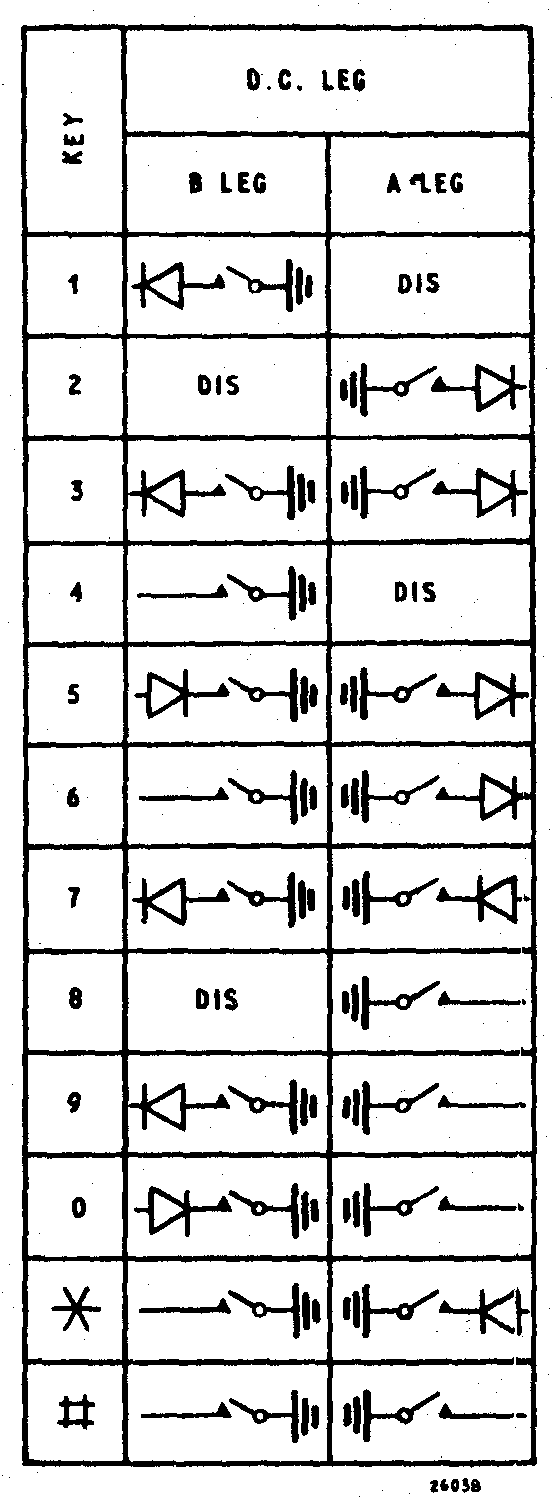 FIG 1 DC CONDITIOND FOR EACH PRESS BUTTON
 No.DEPRESSED NORMAL LP. GLOWS OPERATED LP. GLOWS
FIG 2 TESTER FOR DC CODE ‘C’ KEYPHONES
No.DEPRESSED NORMAL LP. GLOWS OPERATED LP. GLOWS
FIG 2 TESTER FOR DC CODE ‘C’ KEYPHONES